If you have worked with meshes and textures in OpenGL, than you probably have experienced aliasing on textures bound to meshes. Unfortunately OpenFrameworks 008 only supports mip mapping of textures that have compression on them. I usually work with straight jpgs or pngs for my textures, so that is not an option. Recently some friends over at Incredible Machines brought up the issue, so I thought it might be useful to post. Both for other people and myself.
Below is an example of a texture without mip mapping. Notice the jaggedness on the checkered image. It is more apparent when there is a sharp angle from the vertex to the camera.

Now here is the mip mapped version of the texture. Notice how it appears more anti-aliased. (Click to enlarge.)

Anisotropy limits how much “aliasing” is applied between the mip maps. A value of 1 will do nothing, as the value increases so does the appearance of anti-aliasing.
I wrote a convenience function that is based on ofTexture, but includes the mip map and anisotropy functions.
MORE INFO
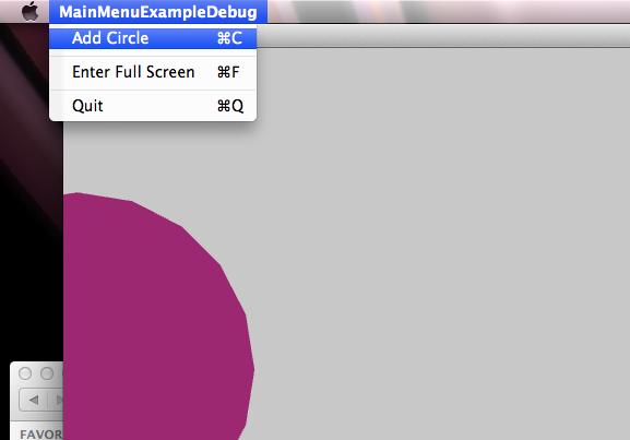
Attached is a project using Openframeworks 008 that allows you to change the menu items in the application for OSX using GLFW.
MainMenuExample
Phone Case Outside

Phone Wallpaper

Download Wallpaper
iPhone 5 ( 640 x 1136 )
iPhone 4 ( 640 x 960 )
Samsung Galaxy 4 ( 1080 x 1920 )
Samsun Galaxy III (720 x 1280 )
iPad 2 (768 x 1024 )
iPad / 3 / 4 / Air (1536 x 1024 )
This post describes the process involved for the Kinected Portrait Series.
A custom OpenFrameworks application captured depth information using the Microsoft Kinect. The depth information was calibrated to a color image that was also captured by the kinect. Below is the raw color and depth information.
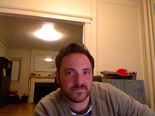
Kinect color image
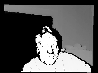
Kinect Depth Data
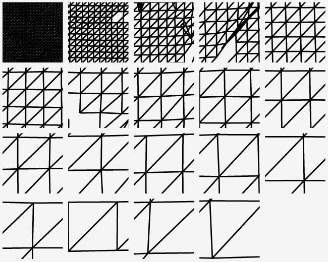
A series of meshes were generated with incremental triangle size from 1 – 19. Below demonstrates the difference in spacing between the different generated meshes, 1 being the tightest and 19 being the loosest.
Various mesh sizes were chosen that allow smooth transitions between tighter meshes and looser meshes. Level 2, 4 and 8 were used to create a composite.
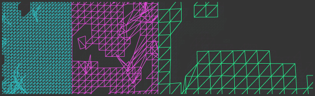
Mesh sizes 2, 4 and 8 from left to right.
The meshes were placed onto the captured color image in photoshop. The tighter meshes denoted the darker areas and the looser ones were utilized for the lighter areas, creating a ‘mesh hatching’ style. Originally the OpenFrameworks application algorithmically blended the meshes based on the lightness of the image, but the process by hand provided a much more pleasing result.
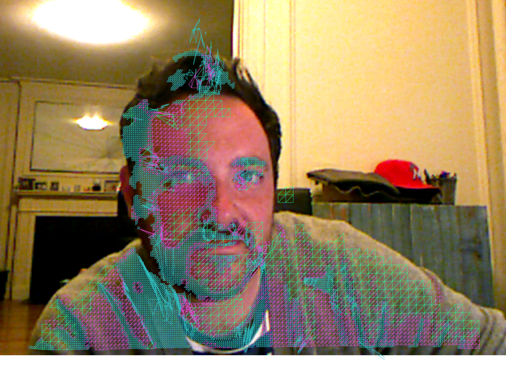
Color Image with Mesh Composite Overlay in Photoshop
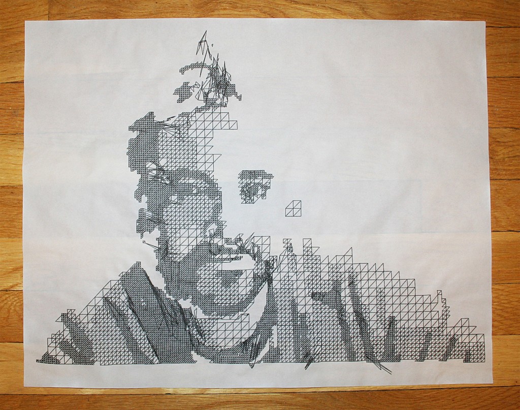
Mesh composite print out on tracing paper
MORE INFO
Glad to have worked on this project with Design I/O. Read more about it here.

